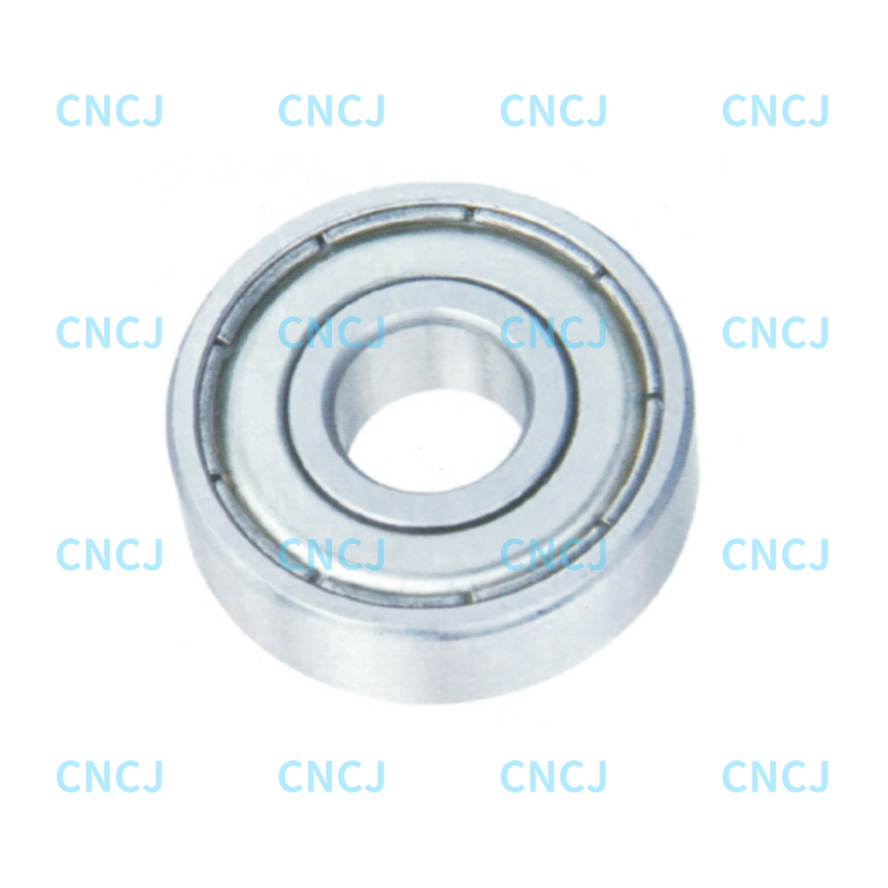
A small bearing in an aircraft flap actuation system carries a combined radial and axial load at altitude, through temperature swings, and with almost no margin for structural weight. Before that bearing is accepted for service, it is loaded beyond its normal working envelope in a controlled test. That exercise is aerospace bearing load testing. Load testing is not a formality; it is the pass-fail gate that separates a component that can be trusted from one that cannot. This article explains the main test methods, the standards that guide them, and the bearing design factors that affect test success.
Why Load Testing Is Critical in Aerospace
Aerospace bearings operate under conditions that most industrial applications never approach. They must survive high static loads during maneuvers, repeated oscillations on the ground, and abrupt shock loads during landing. A single undetected weakness can propagate into a crack, spall, or cage fracture. For this reason, load testing is applied at several levels: incoming material verification, bearing development, and final qualification. It verifies not only whether the bearing can carry the advertised load, but whether the production batch is consistent.
The most common failure modes that load testing exposes include:
Permanent deformation of raceways or rolling elements
Cracks that appear only after load is removed
Abnormal clearance change due to material yielding
Uneven load sharing between rows in double-row bearings
Cage distortion under shock or high acceleration
Load testing also feeds the certification chain. An actuator manufacturer cannot claim a bearing meets a specification without test records. These records must show that the bearing passed the required proof load and, in some cases, a deflection check. Without that evidence, the entire assembly loses its airworthiness case.
Core Load Test Types for Aerospace Bearings
Three test types dominate aerospace bearing verification: proof load testing, deflection testing, and ultimate or limit load testing. Each answers a different engineering question. Proof load testing applies a load higher than the expected operating load to prove that the bearing will not permanently deform in service. Deflection testing measures elastic displacement under a controlled load, which tells engineers how stiff the bearing and housing system will be. Ultimate and limit load testing pushes the bearing closer to its structural limit to establish how much margin remains before fracture.
Comparison of common aerospace bearing load test types
Test Type
What It Verifies
Typical Load Application
Acceptance Focus
Proof load test
Capacity to withstand overload without permanent deformation
Static load above maximum operating load
Dimensions and clearance return to original values
Deflection test
Stiffness and load path under service loads
Controlled ramp to a defined load level
Measured displacement matches predicted value
Ultimate or limit load test
Structural margin before yielding or fracture
Load increased until failure or specified limit
Failure load exceeds the design minimum
In practice, proof load testing is the most common acceptance test because it balances confidence with cost. Deflection testing is used when actuator stiffness must be tightly controlled, such as in flight control surfaces. Ultimate load testing is reserved for critical structural bearings and for validating new designs.
Standards That Make Load Testing Meaningful
Load testing results only have value if the test procedure is defined. Many aerospace procurement specifications reference NAS0331 for bearing proof load testing. Military standards add their own load envelopes and acceptance criteria. SAE ARP5483 provides a rolling element bearing test method for radial limit fracture load testing. These documents set the load rate, hold time, and measurement requirements, so a passing test at one lab can be compared with a passing test at another. When you review a bearing supplier, always ask which standard is used for the proof load test, not just what load value was applied.
What Load Levels Tell You About Bearing Margin
The chart below shows how load levels increase through a typical verification program. Operating load is the baseline from the application. Proof load, usually set above the maximum expected service load, checks elastic stability. Ultimate and fracture limit loads reveal how much margin remains before permanent deformation or separation. The actual multipliers are defined by the customer specification, so these values are illustrative. Reading the chart is simple: the longer the bar, the more severe the load condition that component must survive.
The horizontal bars show how load levels increase through a typical verification program. Operating load is the baseline from the application. Proof load, usually set above the maximum expected service load, checks elastic stability. Ultimate and fracture limit loads reveal how much margin remains before permanent deformation or separation. The actual multipliers are defined by the customer specification, so these values are illustrative. Reading this chart is simple: the longer the bar, the more severe the load condition that component must survive.
Load-Life Relationship and Testing Implications
Load testing would be easier if every failure happened during the first proof load, but most aerospace bearing problems are fatigue driven. The relationship between applied load and fatigue life is steep and unforgiving. A bearing that passes a static proof load can still have insufficient life if the cyclic load is too high for its dynamic rating. The line chart below shows a calculated L10 life curve for a ball bearing as the ratio of applied load to dynamic capacity increases.
This line chart shows the inverse relationship between applied load and bearing fatigue life. The L10 life formula for ball bearings states that life is proportional to the cube of the basic dynamic load rating divided by the equivalent load. As the P/C ratio increases from 0.1 to 0.6, the calculated life falls from around 1000 million revolutions to below 5 million. The curve is steep because even a modest load increase produces a large reduction in life. This is why aerospace load testing never relies on a single point; it maps behavior across a load range. A bearing may show enough static strength at proof load but still have inadequate fatigue life for the required number of flight cycles.
Bearing Type Selection for Load-Heavy Aerospace Systems
Geometry is the first thing that determines whether a bearing can survive a load test. A single-row deep groove ball bearing has a simple load path and is easy to produce, but its ability to handle combined loads is limited. A double-row angular contact ball bearing adds a second row of balls and a defined contact angle, which creates a much stiffer reaction to radial and axial forces. A double-row angular contact roller bearing goes even further, using rollers instead of balls to increase the contact area and reduce contact stress. These differences show up directly in load testing: wider load path, lower deflection, and a larger margin before the material starts to yield. When comparing configurations, our bearing product range provides more detail on load ratings and housing dimensions.
This vertical bar chart compares relative static load capacity for three bearing configurations of similar envelope size. The values are normalized to a single-row deep groove bearing as the baseline. A double-row angular contact ball bearing can roughly double the static load capacity when radial and axial loads act together. A double-row angular contact roller bearing goes further, providing the highest stiffness and load margin in the same package width. This comparison matters for aerospace designers who must fit high load capability into a limited housing. It also explains why extensive load testing is so often specified for double-row configurations.
Double-Row Configurations for Demanding Aerospace Loads
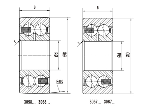
32 and 33 series double-row angular contact ball bearings
32 and 33 series double-row angular contact ball bearings offer a balanced combination of radial and axial capacity for actuation and control surface drives. They are often specified where housing space is limited but the bearing has to hold position against reversing loads. During proof load testing, their two-row arrangement distributes stress across more balls, reducing the risk of localized brinelling. Manufacturers check that both rows share load evenly and that the internal clearance remains stable after the load is released. This makes them a dependable choice for many aerospace secondary control systems.
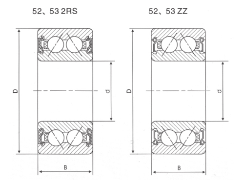
52 and 53 series bearings use a larger contact angle, which shifts more capacity to axial loads. This makes them a natural fit for thrust-dominated aerospace interfaces, such as screw actuators and linkage pivots. Load testing for these bearings should include an axial proof load at the specified contact angle, plus a combined load case that represents the real flight condition. Because contact angle changes with wear and preload, the test records need to track axial displacement carefully. Our detailed analysis of contact angle effects explains how this parameter changes under load.
For the heaviest load envelopes, double-row angular contact roller bearings accept a higher static load without increasing the bearing footprint. Their line contact creates lower contact stress than ball bearings under the same applied force. This becomes decisive when an actuator has to transmit large forces through a compact pivot. The testing process emphasizes stiffness, deflection at load, and the distribution of contact marks across the roller raceways. Where extreme margin is required, these bearings are the strongest candidate.
Load testing can be performed with manual fixtures or automated test rigs. Manual systems are flexible and inexpensive to set up, but they depend on the operator's skill and are difficult to repeat at high volume. Automated systems apply load with precise speed and hold times, record data continuously, and can run around the clock. The radar chart below compares six practical factors. It is not a universal ranking; the right choice depends on volume, part size, and certification requirements. In aerospace production, the trend is toward automated systems because traceability is mandatory.
The radar chart compares manual and automated load testing across six criteria. Accuracy, repeatability, and data capture are clearly stronger with automated rigs. Throughput also favors automation once the system is set up. Manual testing scores higher in setup flexibility because fixtures can be changed quickly for short runs. Cost efficiency depends on volume; for low-volume qualification tests, manual systems may be more economical. The visible shape of the two polygons shows why manufacturers often use both: automated for production sampling, manual for prototype development.
What to Look for in a Load-Tested Bearing
Selecting a bearing for an aerospace program is more than matching a catalog number. The test record is part of the product. Use the following checklist when reviewing a supplier:
Confirm which test standard applies: NAS0331, MIL-SPEC, or an OEM requirement.
Ask for proof load and deflection records, not just static load ratings.
Check that the test temperature and loading direction match your application.
Review the bearing's internal clearance and preload behavior after testing.
Ask the supplier about test rig setup, calibration, and data traceability.
A bearing that passes load testing is not simply a catalog part. It is a verified component with known margin. When you work with a manufacturer that understands both bearing geometry and test method, you avoid surprises during qualification. That is the practical value of aerospace bearing load testing.